
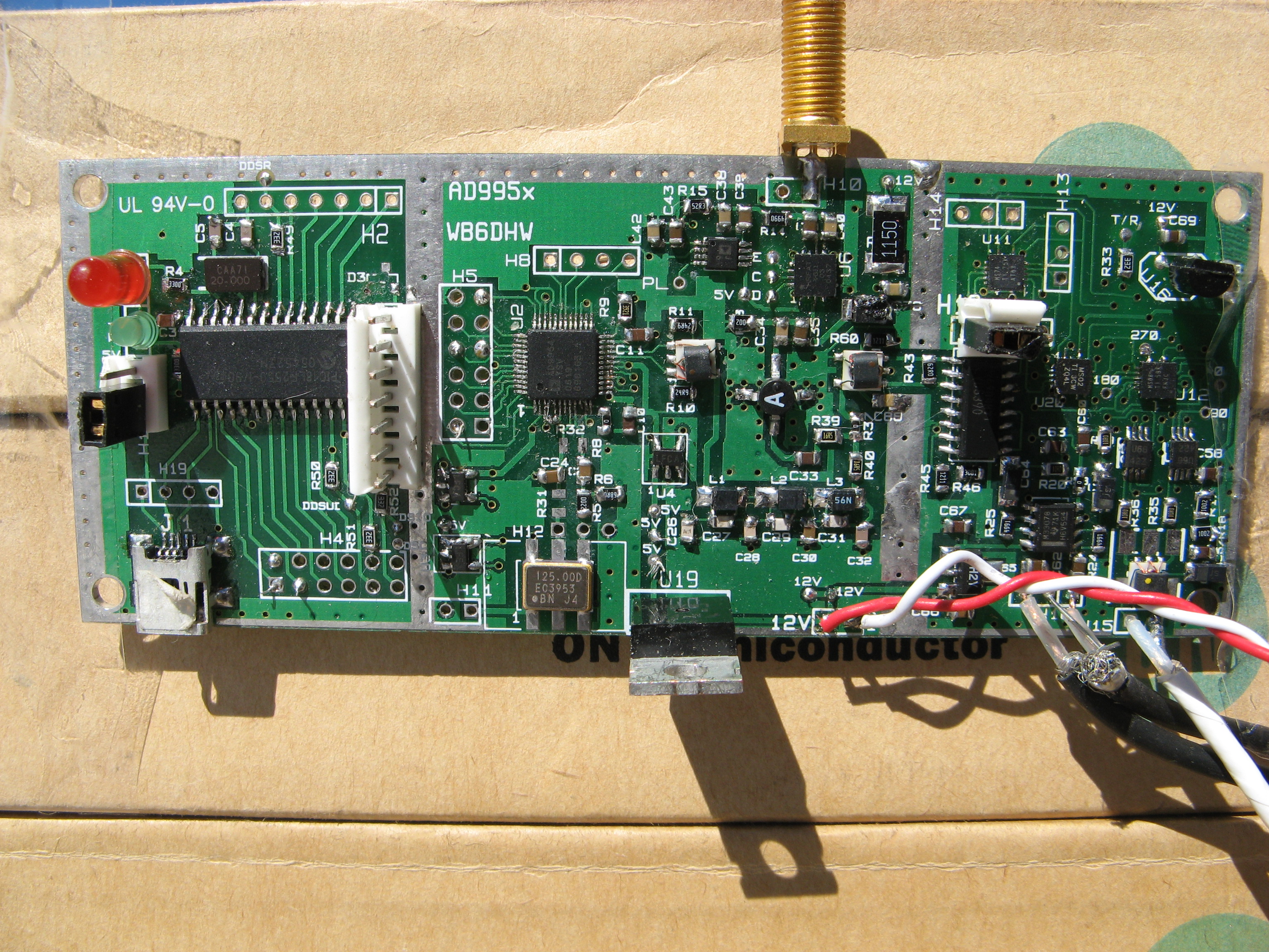
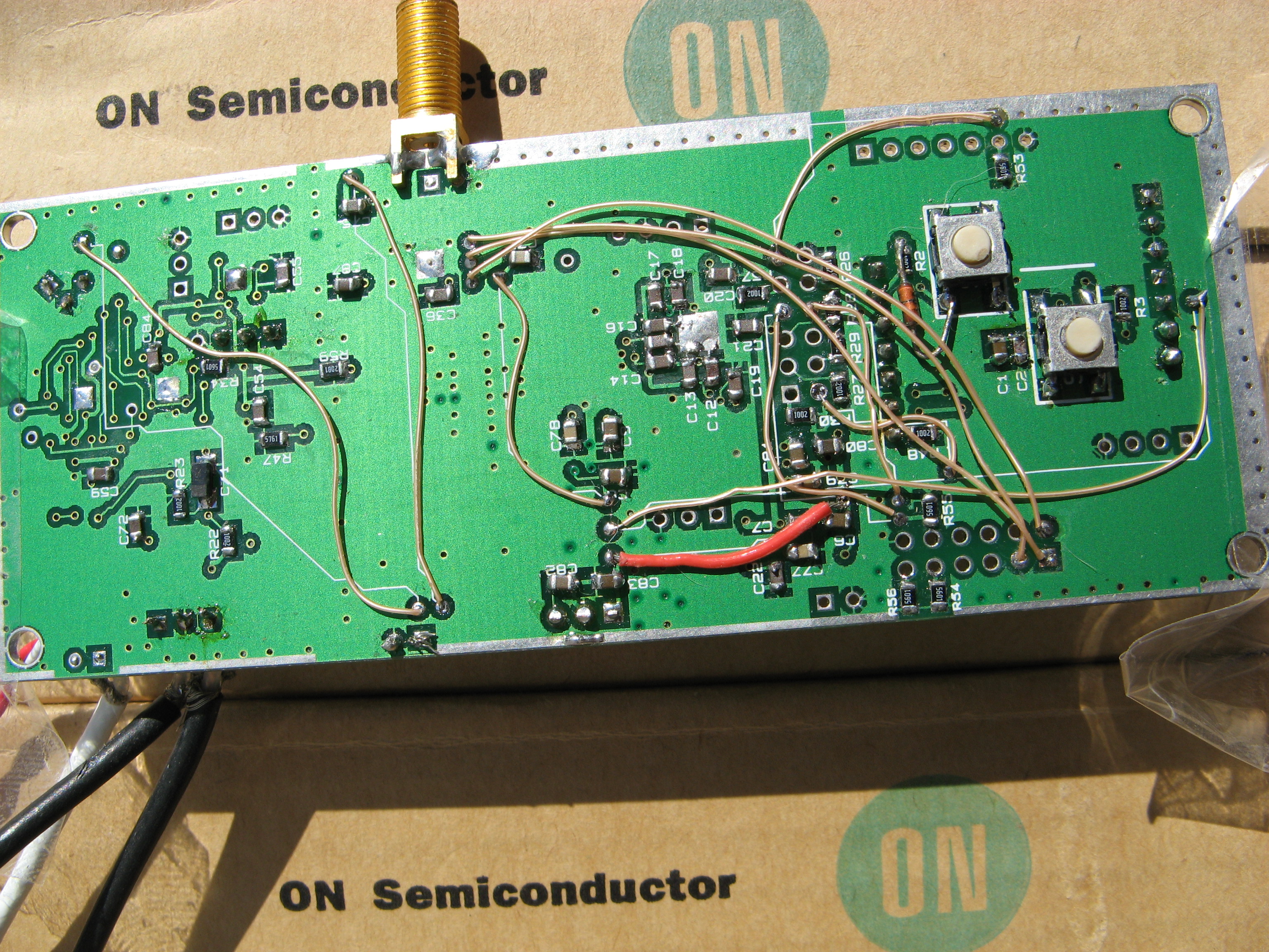
AD995x Board
The AD995x board contains a USB controller, a DDS(AD9951, AD9952, AD9953, or AD9954), a quadrature generator, and a Quad Sampling Detector(QSD). By populating appropriate parts of the board the board may be used for the following: VLF to VHF signal generator with programmable output power. Receiver covering at least VLF to 54MHz or above with connection to a suitable PC and soundcard. The addition of the BPF Board(controllable from the PIC controller) provides a complete receiver. Receiver and transceiver VFO with quadrature generation and receiver control. Spectrum Analyzer with tracking generator VNA(requires slight modification of the QSD circuit to provide DC coupling). For a full description of the operation of the board click on left. For a discussion of this board and associated software being developed join the DDS_Controller Group . I have placed a public parts list at DigiKey. Find it Here . It DOES NOT include T1,T2 or T3 because DigiKey as far as I know does not have suitable alternatives. These on included on the Mini-Circuits_Lab page of the 995x Production BOM . I have included values for 3 different LPF designs depending on the clock frequency used. Uncheck the values for L1,L2 and L3 as well as C26-C32 for the LPF freq. you are not using. I now have my 995x pilot-production board completely assembled and working. I did find that D3(the diode between the PIC reset and 5V) layout was incorrect. No other major problems were found. I have made that correction moved a few parts labels to improve visibility, added pads next to H4 and H2 for the Attenuator and AD8310 connections to the PIC, and added an additional +5V and GND pad for connection to the BPF board. The latest production boards include these changes. Some interactions between different sections of the board have been noted by early constructors. When the quadrature generator is connected, harmonics appear on the analog RF output. Tests will be performed to see if adding shielding will help. If the QSD is needed but not the analog RF output, this is not a problem. Also, if only the analog output is needed, then disconnecting the power to the quarature detector and QSD removes the added harmonics. It was just noticed that the analog RF output is somehow affecting the noise floor of the QSD. If the attenuator is set for maximum attenuation, this effect goes away. Shielding may also help here. This problem is being investigated. Production boards are currently available. A construction/operation manual is currently being prepared. To have boards partially or completely assembled, contact Chris Waldrup Here For USA delivery($9.00 per board shipping included): For Outside of USA Delivery($13.00 per board shipping included):
|