My name is David Brainerd. I am an amateur radio operator with the
callsign of WB6DHW. I live near Kooskia, ID. This is in north-central
Idaho approx. 50 miles east of the Idaho-Oregon-Washington junction.
My main interest is "homebrewing". Since retiring from the US Navy
Civil Service in 1998, I have built several pieces of test gear for my
home electronics lab. These include the N2PK Vector Network Analyzer,
the AADE digital L/C meter, a 3GHz frequency counter, a 0-500MHz power
meter, an IQ HF VFO, the R2 receiver, and the AMQRP Micro 908.
My main ham radio activity is with the Mission Trail Net on
3856KHz LSB at 8pm PDT (7PM PST in winter).
I have decided to turn my homebrew activities into a small home business.
I plan on offering a series of boards and some kits that can be used to
make a complete amateur radio station plus some test equipment.
I have been playing with a homebrew SDR(Software Defined Radio) board with an Si570 programmable
oscillator.
I have it connected to my Thinkpad Notebook using the internal sound card.
To listen to what the Mission Trails Net sounded like on 8-19-08, download the MP3 file on the left.
I was using PowerSDR on the Notebook to do all the massive math required.
The recording was made with the Noise Blasnker On with a 2.7KHz wide LSB filter.
Most of the net members are in Calif., I am in
north-central Idaho. The start of the net was daylight, the end was in darkness.
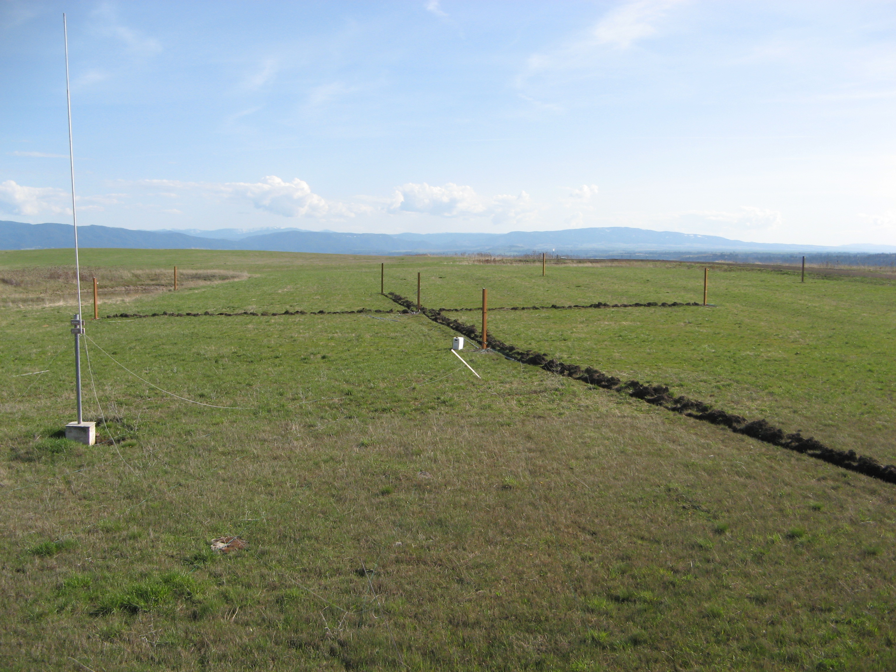
4-Square Antenna
I have started construction of a 4-square antenna. Although primarily for 80 meters, it will also
function on 160 and 40 meters with a couple of additions.
The 4-square is a phased vertical array of four 1/4 wave vertical antennas placed in a square that
is 1/4 wave on a side. All 4 antennas are fed. By adjusting the relative phasing of the 4 antennas,
the antenna beam can be rotated.
I found a good deal on EBay for military surplus 4 foot aluminum mast sections. Seventeen will be used
for each of the 4 verticals. A 34 foot stub will be added approximately 1 foot away from each vertical
for 40 meters. A switchable coil will be added at the base for 160 meters. I am also looking at putting
a trap at the top of each ant and two 20 or 30 foot wires on the rope guys
for top loading on 160 meters to raise the radiation resistance. I have been learning to use 4nec2 to
simulate different configurations before actually building.
The link below is a photo of the support posts for the 4 verticals, the center post for the phasing
network and control relays,
and posts for the rope guys. The array is facing south across the diagonal.
The antenna in the foreground on the left is my 20 meter ground plane.
To see a picture of the supports go here
My wife Barbara's Internet Radio Program:

|